Well I figured out how to use my new my ZKE Tech EBD-A20H Battery Tester and Electronic Load. This video was really helpful: ZKETECH EBD-A20H first look . Also I managed to find the software mentioned in the comments for that video: ftp://randomdl:randomdl@oss.quindorian.org/Random/ZKE-EB_software_1.8.5-0320.zip
The reason I had trouble configuring this electronic load is that I thought the “cutoff voltage” was a maximum setting, but in fact it means cutoff if the voltage drops below this value. That makes sense of course, especially as the main use case for this device is testing batteries. Once the voltage drops below a certain level the battery is dead and you can stop testing.
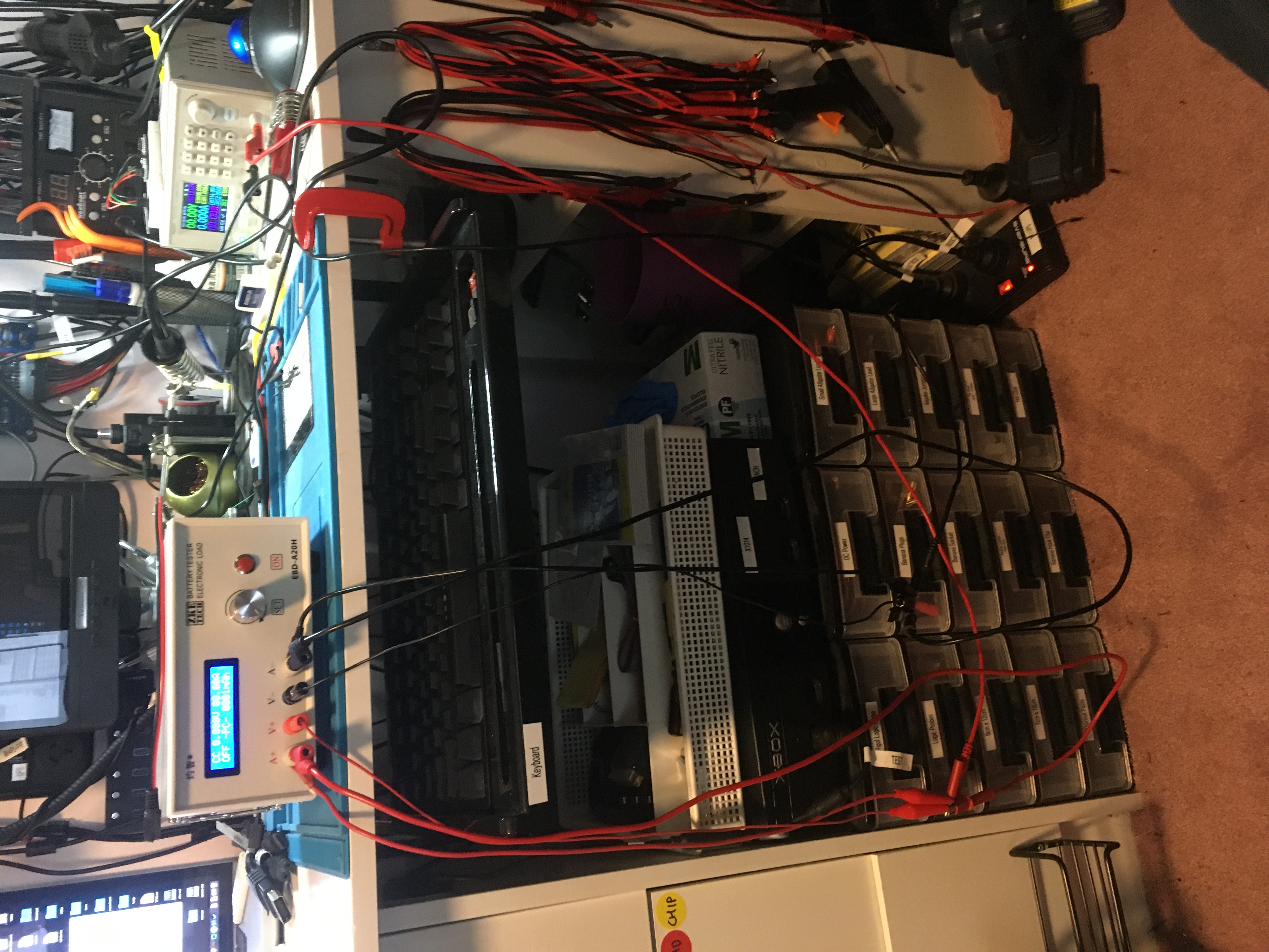
The trick with the wiring is that you can just hook the voltage and current terminals up to the battery / power supply terminals. I think the idea is that you can put the voltage and current terminals in different parts of a circuit, but I don’t really understand that, and for simple battery or power supply testing it seems you can just connect them together.
There are two modes available: Constant Current (CC) and Constant Power (CP). I have managed to get the software working and connected so that should mean I can put this up the back of my bench and control it remotely, which will be handy.
My next video will be me making a cable to fix this mess. Once I have that cable I will make a video demoing the EBD-A20H.